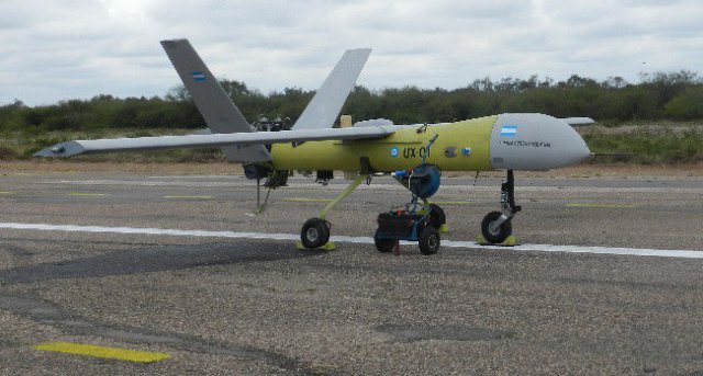
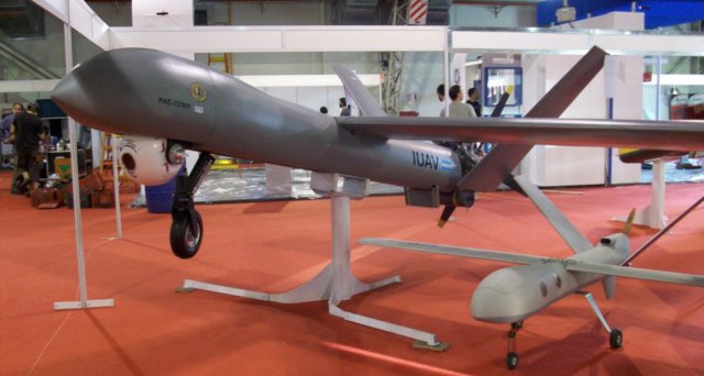
Further to interest from the Ministry of Defence to develop the Argentina Air Force Base in Chamical, Province of La Rioja as the main base exclusively for UAVs in the Argentina Republic, details of the most recent UAV project, the 2A Vigia, have just been released.
Originally developed as the PAE-22365 Project, the Vigia 2A, was devised by the Center for Applied Research (CIA) under the Aeronautical University Institute (IUA) with funding from the Ministry of Science and Technology. This military development demonstrates the intent of the FAA to develop a tactical MALE UAV of national design, unlike the SARA Project, undertaken by the INVAP and the Ministry of Security, which had dual and not specifically military applications. This became known by the FAA, as the FAS-0091 project.
The Vigia 2A is a MALE (Medium Altitude, Long Endurance / medium altitude, long range) Class II, capable of autonomous navigation via satellite link. Framed under the USAR (STANAG 4671 Annex IX) standard development has evolved from a scale model 1: 2 (Class I) which has proven the concept of flight, command and control. Its navigation is controlled from an autopilot by Cloud Cap Technology Piccolo II + GPS / INS with capacity for take-off and automatic landing.It has capacity for radio and satellite link before discontinuation conventionally so the aircraft can return safely to base. One can enter and process a maximum of 1,000 waypoints, check the onboard computer airworthiness and the operation of each system, with the ability to define anomalies detector and emergency situations. This equipment is regulated by export controls of the United States.
For emergency situations, the Vigia 2A has a ballistic parachute as standard equipment.
As payload, it has a usable space of 400x400x800 and up to 50kg. In the prototype, it is ballasted to maintain the center of gravity of the apparatus.
The powerplant is a Japanese HK 700E engine two-cylinder, four-stroke with 60hp maximum power. It is installed in a pusher configuration with a four-blade propeller with variable pitch.
Dimensions:
- Alar Area: 8 m2
- Wingspan: 0 m
- Overall Length: 1 m
- Total height: 92 m
- Fuselage width: 45 m
- Maximum takeoff weight: 330 kg
Plant Propulsora:
- HKS 700E engine, four-stroke two-cylinder, electronic ignition.
- Maximum power: 60 HP @ 6200 rpm
- Reducer: 2.58: 1
- Powerfin propeller blades shovel type 4 BT
- TBO: 1000 hours
Navigation:
- GPS / INS (Autopilot Píccolo 2+) capable of takeoff and landing and automatic link SAT
Emergency:
- Ballistic Recovery parachutes BRS 600 (optional)
performances
- Battery life: 11 hours (4 hours in the 1st prototype.)
- Maximum speed: 115 KCAS
- Maximum altitude mission: 15000 ft
- Time 20 min climb to 15000ft
- Payload: 60 kg
- Maximum takeoff weight 330 kg
- Available power: 1500 W (optional)
El Vigia 2A is a pusher configuration high wing and V-tail, to maximize forward visibility without interference from its propeller. It is equipped with a split flap and aileron, which occupy 20% of the rope.
The flaps are linked by kinematic control with command bar which is actuated by a single actuator. It can be fixed in two positions 30 and 60 degrees.
The ailerons however are individually controlled by a servo electrically directed by the central command.
The group has tail empennage of 9% relative thickness profile NACA 0009 arranged in V with a dihedral of 47 °. The lift occupies 20% of the rope and allows a movement of + 25 / -25. They are led by an electromechanical servo as ailerons and has two operating modes: for direction, and pitching movements antimétricos with symmetrical movements.
The landing gear is tricycle type retractable nose wheel, fixed on the first prototype. The main gear is the Flexible crossbow type and front is fixed with spring and shock absorber, with steerable wheel from the command post.
The arrangement of the fuselage tail wing joint group has been made in order to optimize the aerodynamic and mass balance with a static similar to general aviation in order to facilitate its driving dynamics and stability.
Given the nature of the project and the necessary flexibility for the development of systems and components, the fuselage was designed like a box to allow access and shape changes according to the progress and development of the prototype.
The structure of the fuselage is a conventional metal plate semi-monocoque structure riveted AL 2024-T3 and resistant coating. The coating consists of single curvature panels one generatrix mostly except for the two front top panels, which have two generatrices and are the most complex parts of the assembly.
The strong area is the central area where the wing and the landing gear is taken and machined has 3 frames supporting loads and distributed to the rest of the structure through the coating 6 and stringers. The upper two beams, in most internal fuselage, pass out not to disrupt the strong ribs being in sight.
The same design took into account the need for a free internal space for housing systems and fuel tank.
The front area (from frame front takes wing forward) presents housing retractable front end (not implemented in the first prototype) and the support structure CU-shaped bracket which is covered with the cap fairing removable composite materials. In this area all electronic guidance, control, command and communications is located together with the battery and payload in principle replaced with counterweights in the first prototype.
The fuselage also features in the rear area, inspection covers and access to the box motor control system and fuel.
The fuel system comprises a reservoir (tank 40 liters), connecting hoses, two fuel pumps arranged in parallel, control valve and various sensors (flowmeter, capacitive fuel gauge in the tank and pressure indicators). It is located in the rear of the fuselage, on a tray ready for this purpose and under the wing tank, so as not to alter the position of the cg as empty.
The fuel tank was purpose-designed and built in 5000 series aluminium bent and welded using TIG with a theoretical total volume of 43 liters and form of flattened cylinder. It incorporates the novelty of eliminating the traditional breakwater filling foam inside changing it supports embedded with NAFTA 95 octane unleaded fuel used by the engine.
The other system components were selected from the commonly used and suggested by the engine manufacturer (hoses, connectors, valve, sensors, etc.).
The empennage, both right and left are built in composite, carbon fiber and epoxy resin. Unlike the wing, somewhat more traditional construction, empennage have the latest composite construction concept, Monolithic resistant shells and spars. Cascara has left and right, tough crossbar, crossbar or false rear spar and spar close to the elevators.
The entire assembly is constructed in one piece, by cutting the elevator post.
The shots are metallic, dural 7075 T6.
The landing gear is tricycle type retractable nose wheel (fixed in the first prototype) and crossbow main train type. It was designed by the team and built to order by Grove Aircraft Landing Gear Systems under local requirements. Both wheels Type III 4.00 × 4 as the brake system (calliper and disc) were purchased from the same source.
The front train however was designed and built locally.
Equipment
Aircraft:
- Ballistic parachutes BRS 600
- Disc brakes Grove
- Buoys / lights regulatory position
- GPS / Autopilot Piccolo II +
- Go Pro camera with video link transmitted in real time
- Parameters of engine sensors and flight data transmitted in real time
Ground station:
- 6 Display Led with external cameras and vision of integrated flight data
- Engine instruments: CHT, EGT, RPM, oil pressure, fuel pressure, fuel flow
- Command single-seater flight configuration.
- All tasks are performed in Cordoba, at the premises of the Center for Applied Research, Research and Development of the FAA, Pavilion 77. Tasks such as making parts and pieces generally are outsourced through purchase orders and minor components acquired through direct purchase and older via price competition.During 2015, I conducted tests of acceleration and takeoff abortion, jumping flea, flight primary circuit in manual mode, automatic flight simulation and preparation for certification STANAG 4671..
Photos and graphics: Fuerza Aerea Argentina.
Source: Zona Miltar
Translation by Google


