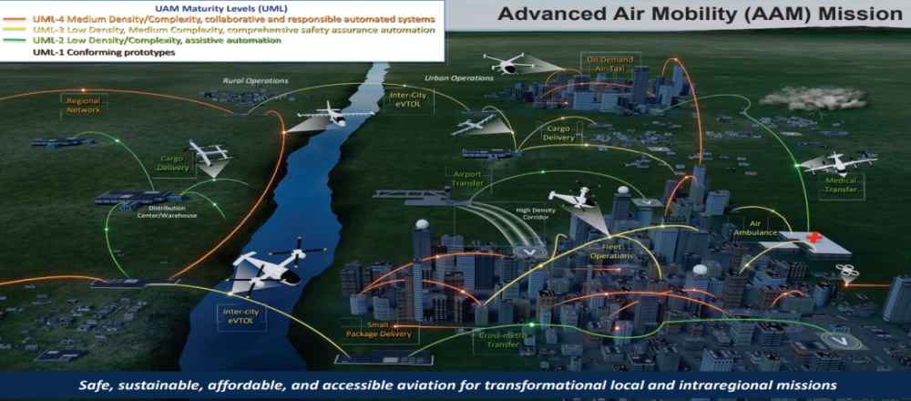
Simulating the response of aircraft to complex wind flows when operating in urban environments is an area of increasing interest for Unmanned Aircraft Systems (UAS) and Urban and Regional Air Mobility (UAM/RAM) vehicles.
Predicting the response of these vehicles to particular wind conditions in close proximity to buildings, such as airports and heliports, is vital for safe operation.
QinetiQ has experience in both wind flow simulations using Computational Fluid Dynamics (CFD) and aircraft 6-Degree-Of-Freedom (6-DOF) flight modelling. It was identified that coupling a built environment CFD flow simulation with an advanced aircraft flight model, incorporating the non-uniform flow field, could be used to create a realistic simulation of the response of an aircraft to wind flow near buildings.
CFD simulations of wind flow in the built environment and over aircraft are well-researched fields. For example, current research investigates the optimisation of UAS flight path planning using CFD simulations to highlight locations within the built environment that would be potentially dangerous for aircraft to operate. Demonstrating that we can model actual response of the aircraft in those areas was the target for this project demonstration.
Task
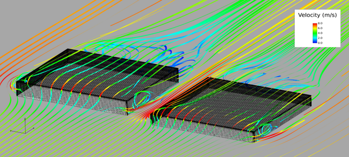
For the simulation, a simplified geometry inspired by the hanger buildings at MOD Boscombe Down was created, with the size and layout modified to introduce a significant flow disturbance. A validated and verified CFD simulation methodology was developed to simulate the wind flow around the hangar buildings in a range of different wind speeds and flow directions. The CFD was processed into a format to be compatible with the aircraft flight model.
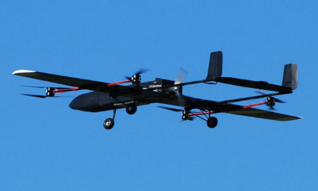
An in-house flight model was developed for a small UAS, the Barnard Microsystems Limited (BML) Panchito. This UAS is capable of vertical take-off and hover in a quadcopter configuration, and of forward motion with traditional wing-borne flight. A simple interaction model was used to calculate the effective velocity vector and rotational rate from the non-uniform freestream flow and the local wind flow.
The flight model incorporated a 6-DOF model of the aircraft with multirotor and airframe aerodynamics, a flight control system and waypoint navigation. This included a run-time system to estimate the local flow field on the aircraft from the non-uniform CFD global flow field.
Result
A live real-time demonstration was presented to Lilium of the simulated response of the small UAS to the CFD modelled wind flow as it operated close to the buildings in different wind conditions. This included a number of different flight phases, including wing-borne flight along a predefined route, transitions to low speed flight and hover, and turning manoeuvres.
The impact of changes in the non-uniform flow around the buildings had a clear effect on the flight of the UAS, particularly in sudden change in wind speed where the aircraft’s flight control system attempted to counteract the effect of the wind to stay on its predefined route.
What was learned?
The key learning point from this project was the capability to integrate complex CFD flow solutions with aircraft flight modelling, enabling us to apply a realistic non-uniform flow field to an aircraft and simulate its response in an environment closer representing the true operating conditions.
Other applications for this capability were identified such as simulations for air to sea integration to advise safe operating conditions, and the potential for the airflow disturbance flight model to be used in a flight simulator to give pilots a realistic simulation of operating close to buildings.
Source: QinetiQ


